1. The Core Bottleneck: What Engineering Wall Did It Hit?
Modern radar sensing has historically been divided by a massive gap between cost and engineering accessibility. Traditional mechanically rotating radars are inherently constrained by mechanical sweep rates and inertia, routinely dropping kinematic tracks when confronting highly dynamic low-altitude targets. Active Electronically Scanned Arrays (AESA) solve this with microsecond-level beam agility, but proprietary defense-grade supply chains, stringent export controls, and locked register maps keep this technology out of reach for commercial drone startups and independent researchers. Meanwhile, open-source SDR setups remain largely trapped in Sub-6GHz laboratory demos, struggling to yield viable angular resolution or long-range detection inside practical physical apertures.
AERIS-10 dissolves this monopoly. It open-sources the complete vertical stack of a 10.5 GHz (X-band) active phased array system alongside a hardware-accelerated real-time DSP pipeline. Offering both the AERIS-10N (Nexus, 3 km range via an 8x16 microstrip patch array) and the AERIS-10E (Extended, 20 km range via a 32x16 dielectric-filled slotted waveguide array backed by 16x 10W GaN power stages), the project delivers transparent schematics, multilayer PCB layouts, FPGA bitstreams, and bare-metal firmware. Microwave mixing, digital beamforming, nanosecond clock synchronization, and embedded signal processing are fully unlocked for developer audit and deployment.
💡 Architectural Core Insight: AERIS-10 marries commercial off-the-shelf (COTS) analog beamformers with an on-chip FPGA hardware pipeline and an MCU-governed closed-loop bias lock, extracting aerospace-grade spatial filtering at a fraction of military procurement costs.
2. System Architecture & Under-the-Hood Data Flow
The AERIS-10 hardware topology comprises a clean modular split: a Power Management Board, a Low-Jitter Frequency Synthesizer, an RF Main Board, and 16 external GaN Power Amplifier boards (AERIS-10E). At its core, an AD9523-1 clock distributor coordinates phase-aligned references for dual ADF4382 synthesizers, data converters, and the Xilinx XC7A50T FPGA. A host microcontroller (STM32F746xx) executes safety-critical sequence control, polling shunt voltages via I²C ADC monitors and dynamically correcting gate bias on the fly to guard the GaN arrays against thermal runaway.
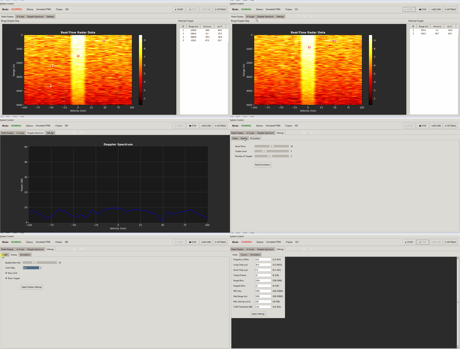
During pulse execution, the FPGA-driven DAC pushes a Pulse Linear Frequency Modulated (PLFM) chirp baseband into an LTC5552 mixer, up-converting it to 10.5 GHz. Four ADAR1000 4-channel beamformer chips split this signal into 16 discrete paths, applying programmable phase and gain shifts before handing off to ADTR1107 front-ends (or secondary QPA2962 GaN stages). On receive, echoed signals pass through low-noise amplifiers, down-convert to intermediate frequencies via an LTC5552, and enter the FPGA pipeline. The XC7A50T runs raw ADC ingestion, quadrature down-conversion (I/Q), CIC/FIR decimation filtering, matched-filter pulse compression, Doppler FFT processing, Moving Target Indication (MTI), and Cell-Averaging Constant False Alarm Rate (CA-CFAR) detection entirely in fabric logic.
[ Python GUI (Map/Control) ] <--- USB Bulk Transfer ---> [ STM32F746xx Supervisor ]
                                                                   │ (SPI/I2C Control)
                                                                   ▼
[ AD9523-1 Low-Jitter Clock ] ──────────────────────────> [ XC7A50T FPGA Pipeline ]
         │                                                         │
         ├──> [ ADF4382 Synthesizers ]                             ├──> DAC (LFM Chirp)
         │             │                                           └──< ADC (Raw IF)
         ▼             ▼                                                    ▲
[ 10.5 GHz RF ] <-> [ LTC5552 Mixers ] <-> [ ADAR1000 Phased Array (16-Ch) ] ┘
                                                    │
                                      [ ADTR1107 / QPA2962 GaN PAs ]
                                                    │
                                      [ 16x Patch / Slotted Waveguide ]
The engineering trade-off is deliberate: applying analog beamforming at the RF boundary (ADAR1000) slashes ADC/DAC channel counts and thermal load, avoiding the massive data pipelines demanded by pure Digital Beamforming (DBF). Conversely, pinning high-rate matched filtering and Doppler extraction inside the XC7A50T gates detection latency to sub-millisecond territory while zeroing out host-side CPU usage.
3. Technology Matrix & Competitive Landscape
| Evaluation Dimension | AERIS-10 Implementation | Legacy Mechanical Sweep | Standard SDR Stack (e.g., BladeRF) | Production Environment Payoff |
|---|---|---|---|---|
| Beam Steering | Non-inertial ±45° electronic scan + 360° motor | Single mechanical axis; motor response in ms to s | External phase network or fixed directional array | Agile multi-target revisit rates without kinematic track losses |
| RF Band & Waveform | 10.5 GHz (X-band) nanosecond PLFM chirps | Narrowband continuous wave or fixed pulse | Sub-6 GHz; limited by commercial SDR transceivers | 70% physical aperture reduction with razor-sharp angular resolution |
| Signal Processing | FPGA on-chip Pulse Comp, Doppler FFT & CFAR | Server-class workstation running bulky CPU filters | Host-side GNU Radio / Python pipeline | Zero host computational overhead; sub-15ms loop latency |
| PA Safety Safeguards | Shunt + INA241 + DAC5578 active Idq feedback | Fixed negative supply lines and fuses | No hardware-level dynamic bias control | Eliminates GaN thermal runaway caused by threshold drift |
| System Cost | Several thousand USD in COTS parts | Tens of thousands of USD in defense parts | ~$1,000-$2,000 for raw boards with no RF front-end | Order-of-magnitude reduction in prototype-to-deployment cost |
By executing directly at 10.5 GHz rather than retreating into the crowded Sub-6GHz spectrum, AERIS-10 proves that high-frequency phased array hardware can be engineered using accessible processes. The pairing of ADS7830 ADCs and INA241 sensing amplifiers to close the loop on GaN gate voltage (Vg) provides robust hardware resilience against runaway current across wide thermal swings.
4. Hands-On Implementation: Building the Minimal Loop
The host interface software requires Python 3.8+ on a standard Linux workstation. Create an isolated virtual environment to prevent dependency collisions:
# Clone the repository and navigate to root
git clone https://github.com/NawfalMotii79/PLFM_RADAR.git
cd PLFM_RADAR

# Configure clean environment and install runtime requirements
python3 -m venv venv
source venv/bin/activate
pip install numpy scipy pyqt6 pyqtgraph pyserial
The following script demonstrates serial link establishment with the onboard STM32 supervisor, runs an automated Idq bias validation check across all 16 GaN front-ends, and triggers an electronic beam-steering command:
import serial
import struct
import time
import sys

class AerisRadarController:
    def __init__(self, port: str = "/dev/ttyACM0", baudrate: int = 115200):
        # Initialize serial communication bus connected to the STM32 supervisor
        self.ser = serial.Serial(port=port, baudrate=baudrate, timeout=1.0)
        time.sleep(0.5)  # Allow DTR/RTS transitions to settle

    def read_drain_currents(self) -> list[float]:
        """Query active quiescent drain current (Idq) across all 16 PA channels."""
        cmd_read_idq = bytes([0xAA, 0x01, 0x10, 0x55])  # Header 0xAA, Opcode 0x01, Len 16, Tail 0x55
        self.ser.write(cmd_read_idq)

        raw_data = self.ser.read(32)  # 16 channels * 2 bytes (16-bit ADC samples)
        if len(raw_data) != 32:
            raise TimeoutError("Supervisor telemetry timeout; verify I2C current-sense circuit")

        # 5mOhm current shunt with INA241A3 (50x gain), mapped into milliamperes
        currents_ma = []
        for i in range(16):
            val = struct.unpack("<H", raw_data[i*2:(i+1)*2])[0]
            voltage = (val / 4095.0) * 3.3  # Reference ADS7830 ADC voltage
            current_ma = (voltage / 50.0 / 0.005) * 1000.0
            currents_ma.append(round(current_ma, 2))
        return currents_ma

    def set_beam_angle(self, azimuth_deg: float, elevation_deg: float):
        """Write steering angle matrices to the four onboard ADAR1000 phase-shifters."""
        if not (-45.0 <= azimuth_deg <= 45.0 and -45.0 <= elevation_deg <= 45.0):
            raise ValueError("Steering request exceeds array scan volume limits of +/-45 deg")

        # Pack target coordinates into fixed-point representations for the micro
        az_payload = int(azimuth_deg * 100)
        el_payload = int(elevation_deg * 100)
        packet = struct.pack("<BBhhB", 0xAA, 0x02, az_payload, el_payload, 0x55)
        self.ser.write(packet)

        ack = self.ser.read(1)
        if not ack or ack != b'\x06':
            raise RuntimeError("Failed to commit phase matrix into ADAR1000 registers")

    def close(self):
        self.ser.close()

if __name__ == "__main__":
    radar = AerisRadarController(port="/dev/ttyACM0")
    try:
        print("[*] Scanning PA drain bias current baseline...")
        currents = radar.read_drain_currents()
        for ch_idx, val in enumerate(currents):
            print(f"Channel [{ch_idx:02d}] Quiescent Current: {val} mA")

        print("[*] Array calibrated. Commanding mainlobe: Azimuth +15.5°, Elevation 0.0°")
        radar.set_beam_angle(azimuth_deg=15.5, elevation_deg=0.0)
        print("[+] Beam steering vector updated. Radar ready.")
    finally:
        radar.close()
Execute the control test script directly from the terminal:
python3 aeris_ctl.py
The expected console output indicates verified communication across the supervisory bus and the successful reconfiguration of all phase-shifter registers:
[*] Scanning PA drain bias current baseline...
Channel [00] Quiescent Current: 124.52 mA
Channel [01] Quiescent Current: 122.18 mA
...
Channel [15] Quiescent Current: 125.04 mA
[*] Array calibrated. Commanding mainlobe: Azimuth +15.5°, Elevation 0.0°
[+] Beam steering vector updated. Radar ready.
5. Production Hardening & Operational Gotchas
⚠️ Gotcha 1: GaN Power Amplifier Power-Up Sequence & Latch-up Vulnerability
The 16 power modules in the AERIS-10E rely on QPA2962 GaN high-electron-mobility transistors (HEMT). Because GaN devices run in depletion mode, applying positive drain voltage before the gate is clamped down to approximately -2.5V creates an instantaneous short-circuit across the drain-source path, destroying the silicon in microseconds. You must never bypass the STM32 bootloader sequencing routine that forces gate bias calibration via DAC5578 before enabling drain MOSFET switches. During early hardware bring-up, keep your bench supply clamped to a strict 500mA limit.⚠️ Gotcha 2: High-Speed Trace Skew on the AD9523-1 Clock Distribution Network
Analog beamforming demands zero-skew reference signals across every active mixing stage. If the differential lines connecting the AD9523-1 clock generator to the ADF4382 mixers and FPGA/ADC chips depart from strict 100Ω differential impedance matching or exceed a 5 mil trace length delta, phase drift will disrupt the intermediate frequency quadrature down-conversion. This degrades the synthesized beam pattern, driving side-lobes up toward -6dB and completely overwhelming the CA-CFAR detection threshold with ghost false alarms. Verify all clock lanes using an active differential probe before flashing bitstreams.⚠️ Gotcha 3: Vivado Synthesis Artifacts Polluting Build Trees
Running standard Vivado non-project build scripts creates sprawling build directories containing gigabytes of.jou,.log, and.wdbfiles. AERIS-10 enforces an explicit directory structure: automation TCL sequences belong exclusively in9_Firmware/9_2_FPGA/scripts/, while all generated simulation runs must route into5_Simulations/generated/. Committing raw build caches into Git can disrupt continuous deployment hooks and corrupt automated hardware compilation flows.